Workflow LibraryView Control & Graphics
Control View Range and Cut Plane
View range and cut plane controlled so plans show what you intend.
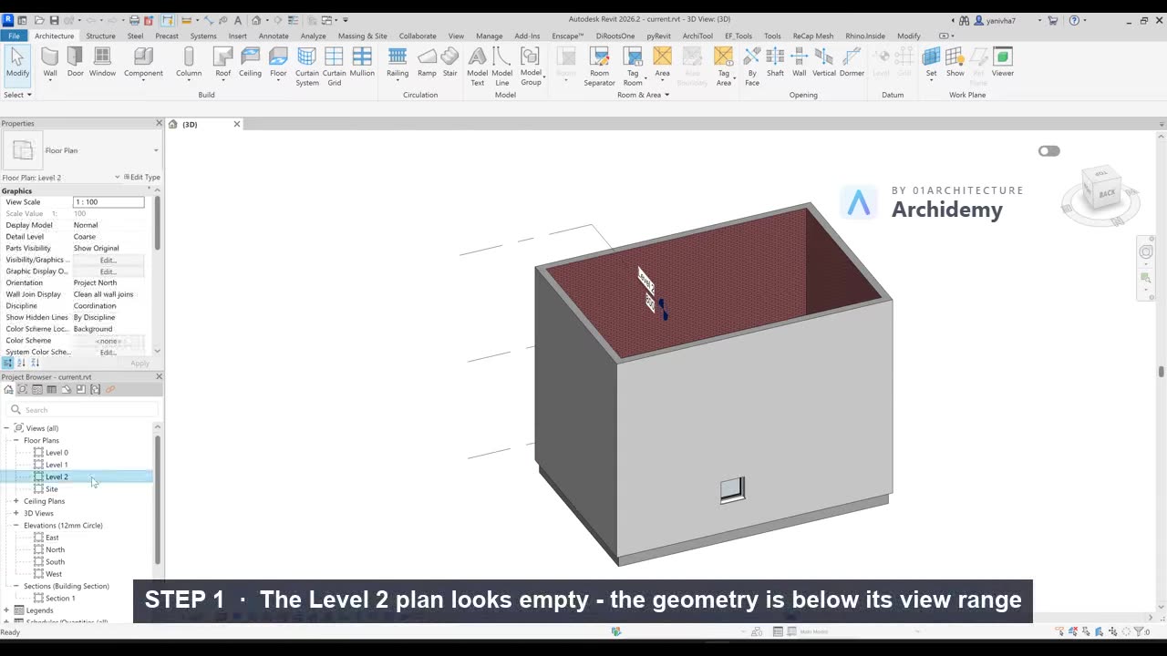
The recorded clip is for signed-in members. The written steps are below.
Sign in to watch- Open the plan view that isn’t showing the expected geometry (e.g. Level 2).
- In the Properties of that view, scroll to View Range and click Edit….
- Understand the parameters:
- Top and Cut Plane: where the section plane is located.
- Bottom: lower boundary of primary view.
- View Depth: extra depth below the bottom, for additional visibility.
- Typical architectural floor plan:
- Cut Plane ≈ 1.20 m above the level.
- This height is used so windows, doors, and openings are cut and visible.
- Adjusting to see lower geometry (e.g. context below a high roof level):
- Set View Depth → Unlimited or to Level 0.
- Click OK.
- The geometry from lower levels should now be visible when looking down from your high roof level plan.
- Understand missed windows:
- If a window’s sill is above the cut plane (e.g. sill at 2.00 m while cut plane is 1.20 m), the window won’t be cut, and may show only as an overhead symbol or not at all.
- Adjust the Cut Plane or the window height to show it correctly.
Tip: If a plan looks empty, always check View Range and Crop Region before assuming something is wrong with your model.
Taught in
- BIM + Computational Workflow · 2023 — original class recording lives there.
Was this lesson helpful?